

0 引 言
变重力池沸腾(vgBoiling)是中国空间站China Space Station(CSS)问天实验舱变重力科学实验柜首批两项科学实验任务之一,利用变重力科学实验柜离心机旋转形成的0.01~2.00 g(g为地面重力加速度)可主动调控的宽域重力环境,在同一个加热器上实现不同重力条件下的稳态和准稳态池沸腾现象,研究不同重力条件下池沸腾传热性能与气泡动力学规律,揭示重力对沸腾传热性能的影响机制[1]。
多功能集成微加热器(Multi-functional Integrated Micro-heater,MIM)[2]采用微机电系统(Micro-Electro-Mechanical System,MEMS)技术加工集成了气泡激发、温度测量和功率输入等功能,并采用COB(Chip-On-Board)封装技术形成独立器件,是变重力池沸腾实验装置中的关键部件。多功能集成微加热器加热基板采用石英玻璃,加热基板上下表面加工出特定的金属铂薄膜电阻,并通过特定电控策略来实现相关功能,其中温度测量功能的实现利用了金属铂薄膜电阻的温度敏感系数大和稳定性强的特点。考虑到实际加工过程中引入铬、镍以强化金属铂薄膜和石英玻璃基板间的结合力,薄膜厚度(特别是加热面上局部温度测点的金属铂薄膜厚度)较小,使用中的薄膜电阻温度特性会偏离标准铂电阻曲线,以及可能存在的历史漂移现象,需要对多功能集成微加热器温度测量元件进行经常性的在轨标定。Wu等[3]、Liu等[4]针对“实践”十号(SJ-10)返回式卫星单气泡池沸腾实验(SOBER-SJ10)中集成微加热器温度标定需求,提出了基于不受沸腾加热影响的同一飞行实验阶段在轨实验数据的同步标定方法,利用与所要测量温度尽可能近的实验数据进行局部温度传感器的标定,以正确反映其温度-电阻关系,成功实现了对空间实验中集成微加热器温度测量数据的反演计算。
虽然vgBoiling-CSS实验任务中所研制的多功能集成微加热器继承了SOBER-SJ10实验所用集成微加热器设计思想和制备方法,设计参数与工艺流程的调整优化仍带来了一些明显的性能差异,在显著提升性能稳定性和重复性的同时,电阻-温度关系的非线性效应有所增强。因此,本文基于vgBoiling-CSS空间站飞行实验数据,分析多功能集成微加热器加热基板上下表面局部温度测点和主加热器输出参数变化特征,完善标定方法,以获得准确的温度标定结果,从而支持vgBoiling-CSS空间站在轨实验数据的反演与分析。
1 多功能集成微加热器及其标定流程

图 1 多功能集成微加热器基板结构示意图Fig.1 Schematic diagram of the substrate structure of the multi-functional integrated micro-heater |
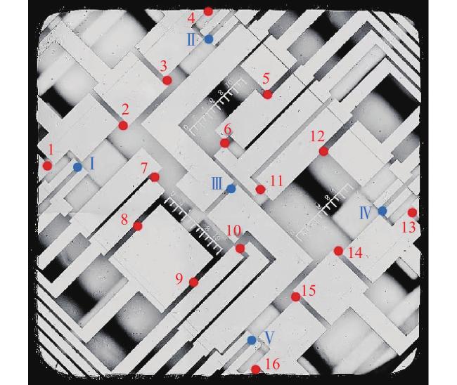
图 2 加热基板上表面气泡激发器与局部测温点分布图Fig.2 Distribution of bubble triggers and local temperature sensors on the substrate's top surface |
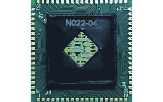
铂电阻因其在广泛温度区间内稳定的温度-电阻相关性,成为适用于高精度温度控制和高温应用场景的理想选择。然而在温度波动的过程中,由于陶瓷基板、铂薄膜、保护层及釉层等各层材料的热膨胀率存在差异,导致各层膨胀程度不同,从而在铂薄膜上产生应力,最终引起铂电阻值的变化,表现为温度系数的调整。此外,测量电路的特性同样会对铂薄膜电阻的温度-电阻性能产生一定影响。因此,局部温度测量的电阻-温度对应关系需要通过标定来确认。
多功能集成微加热器温度测点电阻的测量采用三线制测量方法,以消除引线对测量结果的影响。加热基板上表面的局部温度测点被分为4组串联,并利用恒流源提供微弱电流,在确保电阻测量灵敏度的同时,抑制焦耳热效应对实际温度场的影响。电路原理如图4 所示,其中,参考电阻Rref采用低温度系数的高精度电阻。因此,每组4个局部温度测点(N=4)的电阻可表示为:

加热基板下表面主加热器采用可调控电压大小的恒压源供电,以实现多功能集成微加热器加热功率输入的调控。图4 为局部温度测点电阻测量电路原理示意图,鉴于主加热器电阻值的变化同样直接反映了其温度的变化,因此采用三线制电阻测量方法来确定主加热器电阻,与传统方法不同的是,此处恒流源被脉宽调制(Pulse Width Modulation,PWM)调压电路所取代,且参考电阻前仅有一个的主加热器电阻(即N=1)。
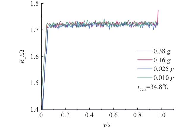
为了抑制主加热器因焦耳热效应引起的温度提升,并确保数据采样精度和电阻测量的灵敏度,通过预实验确定了数据获取方法,即PWM调压电路以10%负荷输出并持续1.0 s,在此期间测量并记录主加热器电阻相关数据。主加热器通电后电阻变化特性如图5 所示,显示了液体处于稳定的常温状态时,主加热器在PWM调压电路以10%负荷短时开启后的电阻变化情况。可以看出,主加热器电阻读数在主加热器通电后约0.05 s即可达到稳定,但在接近1.0 s时存在出现升高的现象,这表明焦耳热效应开始显现,导致电阻偏离了液体温度对应的阻值。不同重力条件下的测试表明,主加热器电阻示数与重力水平无关。在实验模拟的重力范围内(0.01 g~0.38 g),主加热器电阻示数与重力水平无关;为稳妥起见,主加热器标定所采用的电阻值取PWM调压电路10%负荷输出后0.1~0.8 s内的平均值。
空间站在轨实验中,实验工质为氟化液FC-72,多功能集成微加热器加热基板上下表面上的局部温度测点和主加热器标定,是通过实测电阻阻值和同步记录的液池内2路液体温度的平均值进行比较来确定的。液池温度的调节是通过液池侧壁外的预热电阻膜加热实现的,并且基于液池内实验工质温度测量数据进行反馈控制,以确保多功能集成微加热器附近温度场的均匀性和稳定性。液池内实验工质温度采用Keller公司生产的PAA-4LD型数字绝压传感器测量,其测量范围为0~100℃。在装置发射至空间站之前,通过地面标定确定其测量不确定度为0.4℃[5]。具体在轨标定测试流程如下:
(1) 启动离心机并维持稳定的重力水平。
(2) 启动变重力池沸腾实验装置,持续记录液体温度作为标定温度的依据;同时,记录4组局部温度测点回路相关数据,作为室温环境下的电阻计算依据。
(3) 预热液池内部实验工质,将液体温度依次控制在30、35、40、45、50℃,共6个温度阶梯,这与空间站不同重力条件下的池沸腾传热试验温度设定状态相同。在每个温度阶梯下,确保液体温度达到预设值后维持30 min,以保证多功能集成微加热器与液体达到热平衡并保持稳定。
(4) 在每个设定的液体温度(包括未预热时的室温环境)达到稳定后,将PWM调压电路以10%负荷开启并持续1 s,记录主加热器回路相关数据。
2 在轨标定结果
铂电阻的电阻-温度特性在高于0℃温区常用二阶形式的Callendar-Van Dusen(CVD)方程[6]描述:
式中,R0、A和B均为待标定的经验系数;t为温度(℃)。标定实验中,统一采用2路液池温度传感器数据的平均值作为各个测点电阻对应的参考温度。
一旦确定了上述经验系数的数值,即可由式(2)和各个测点的实测电阻值R计算出对应的测点温度:
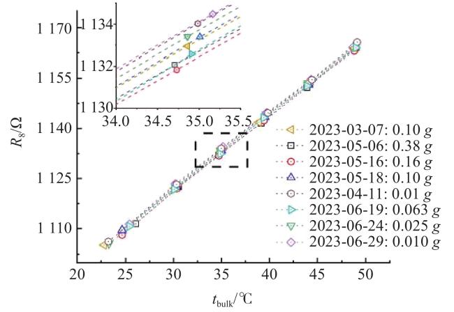
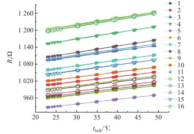
图 6 若干典型在轨标定实验中局部温度测点8#电阻随液池温度的变化Fig.6 The variation in resistance of the local measurement senor 8# with bulk liquid temperature during several typical on-orbit calibrations |
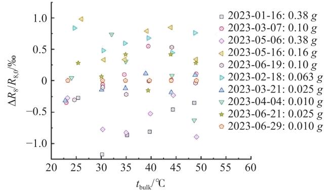
图 7 局部温度测点8#电阻相对偏差的历史变化Fig.7 The historical relative deviation of the resistance local temperature senor 8# |
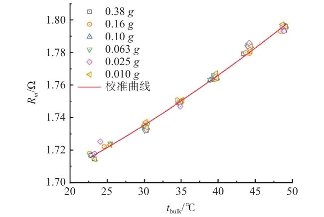
主加热器的标定采用了相同的方法,其电阻-温度关系如图9 所示,该图呈现了主加热器电阻随液体温度的变化的在轨标定实验结果。主加热器电阻相对偏差的历史变化如图10 所示,则展示了主加热器电阻相对偏差在半年时间内的演变过程,其中,Rm,0同样是基于图9 数据采用式(2)拟合所得系数给出的预测阻值。可以看出,在半年内的重复实验中,主加热器电阻相对偏差始终维持在≯4‰范围内,未表现出明显的时间效应和重力效应。因此,可以通过累积更多的空间站在轨标定数据,可以有效消除单次标定数据的偶然误差。最终的标定结果如图11 所示,其中实线代表主加热器温度在轨标定曲线预测结果。
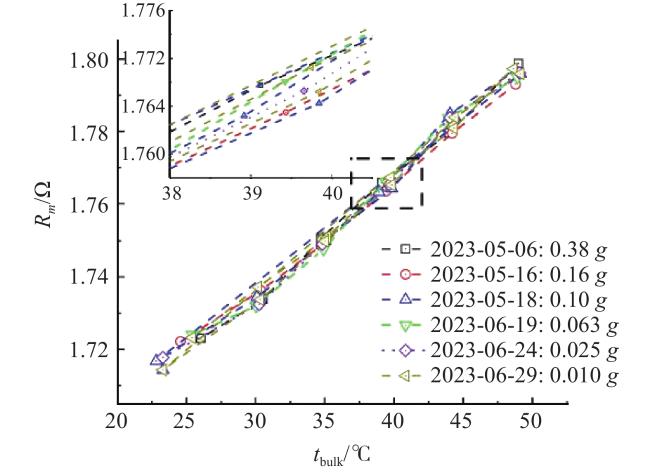
图 9 在轨标定实验中主加热器电阻随液体温度的变化Fig.9 The variation in the main heater resistance with bulk liquid temperature during several typical on-orbit calibrations |
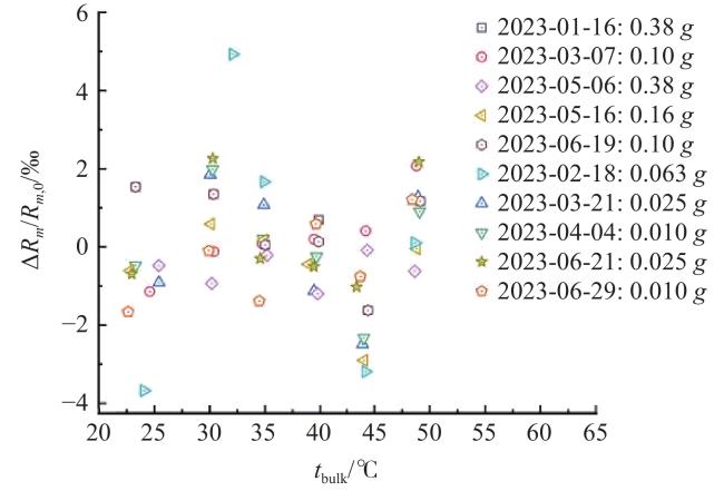
图 10 主加热器电阻相对偏差的历史变化Fig.10 The historical relative deviation of the resistance of the main heater |
如前所述,多功能集成微加热器局部温度测点和主加热器温度-电阻特性均与重力水平无关,且不存在加热历史效应。因此,可以通过累积历次空间站在轨标定数据,甚至筛选沸腾实验工况中不受沸腾加热影响的数据,来降低温度测量的不确定度[7]:
式中,ti为基于标定实验中的基准温度即实测液体温度值,而t为根据式(3)由实测电阻反演求得温度计算值,N为同一测点样本数。这里,N=47,即在轨标定试验次数。
3 单相自然对流传热性能
当主加热器启动后,加热基板内将处于瞬态的热传导过程。当上下表面温度及其温差趋于稳定时,加热器内部的温场将达到稳定状态。此时,由加热基板传递给实验工质的热流可以通过傅里叶定律来计算,即:
式中,λ为石英玻璃基板的导热系数;h为基板厚度;tb和tt分别为基板下表面和上表面的温度;tt可由16路局部温度测点数据平均得到。原则上,式(4)仅适用于一维稳态导热问题,但在特定情况下,也可以扩展应用于准稳态导热问题。
空间站典型常规池沸腾实验中,基板温度和热流密度的变化情况显示了一组典型的空间常规池沸腾实验结果。在重力水平为0.063 g,液池压力为43.12 kPa,液池温度为24.2℃的条件下,液体过冷度(即液池压力对应的实验工质饱和温度与液池温度之间的差值)为9.0℃,如图12 所示。整个实验过程中,系统始终处于单相状态。可以看出,当主加热器开始加热后,上下表面温度迅速上升,随后温升速度减缓,通常在设定的加热台阶中期趋于稳定。在大部分时间里,基于遗传算法[8]和稳态傅里叶定律(即式(4))计算得到的热流密度(分别记为qg和qs)保持了较好的一致性,这表明实验中加热基板内的传热过程达到了准稳态。
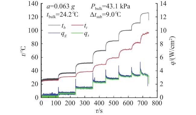
表 1 常用单相自然对流传热经验关联式Table 1 Common-used empirical correlations for single-phase natural convection |


式中,a表示当地重力加速度;β、ν和α分别表示液体工质的热膨胀系数、运动黏度和热扩散系数;tbulk表示液池温度,加热区等效直径Lh由其有效加热面积A及周长P确定,即Lh=A/P。
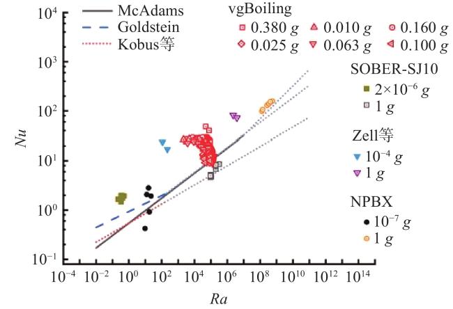
如图13 所示,本实验在空间站0.01~0.38 g模拟重力范围内所得到的自然对流实验结果,整体上与常用经验关联式预测值相符,与文献报导的同类微重力实验结果也处于相同范围。不过,空间站变重力科学实验柜模拟重力存在0.001 g或设定重力值的1%范围的波动[15],这种波动会促进流体运动,引起一定的传热强化效果。这反映在图13 中,即本实验所得数值相比于经验关联式的预测值略显偏大。在所有同类实验中,NPBX[9]的实验数据与经验关联式的预测整体趋势更为一致,但其在国际空间站上的数据同样有着显著的离散度,同样显示了空间站残余重力扰动的影响难以完全消除。另一方面,在Zell等[10]抛物线飞机实验中,残余重力的波动更明显,而其实验结果同样明显偏大,基本位于本实验数据的外缘,进一步表明实验结果对经验关联式预测值的偏离来源于微重力实验平台重力的非恒定性。因此,本实验结果和常用经验关联式的预测值相比,虽然存在一定的数值偏差,但整体传热特性相似,与文献报道的同类微重力实验结果相符,表明本文给出的多功能集成微加热器温度标定结果合理,变重力沸腾实验装置性能可靠,可以获得可信的不同重力条件下池沸腾传热性能数据。
4 结 语
变重力池沸腾实验已经在中国空间站问天实验舱的变重力科学实验柜中顺利开展了一系列在轨实验。基于空间站在轨实验数据,并以沸腾液池内液体温度的实测数据为基准,对多功能集成微加热器的16路局部温度测点和主加热器的电阻-温度特性曲线进行了标定。这些标定结果将用于对变重力池沸腾空间站在轨实验数据开展反演分析。主要结果如下:
(1)多功能集成微加热器在轨标定实验数据表明,16路局部温度测点和主加热器的电阻-温度关系不存在时间(加热历时)效应和重力效应。
(2)局部温度测点和主加热器温度的测量不确定度分别不大于0.5℃和0.9℃。
(3)在变重力池沸腾空间站进行的在轨实验中,不同重力条件下的单相自然对流传热特性与经典关联式预测及同类实验数据一致,验证了在轨实验结果的可靠性。